


- To work with 71 and 77 PCMflash modules, the BOOT switch must be in the AUTO or MANUAL position.
- In MANUAL mode – power must be supplied by the switch on the PowerBox, and not from an external source.
- In GPT mode, it allows you to work with 5V and 12v signals, as well as with differential inputs without using capacitors.
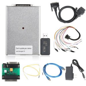
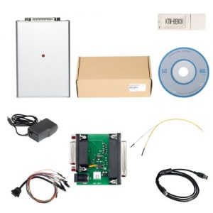
PCMFLASH Powerbox,ECU power control tool with Bench cable
$35.00
Description
PCMFLASH Powerbox is designed for connecting an ECU to a PCMFLASH ECU Programmer or J2534 device ,That provides manual or automatic power control of the ECU.it also will shaping of the following signals: RESET, BOOT, CNF1, GPT1, GPT2, WATCDOG.
PCMFLASH POWERBOX compatible in the automatic mode with the programming tools which use:
- BOOT-OEM12,
- 12 pin OBD-II;
- L-LINE,
- 15 pin OBD-II.
The PCMFLASH Powerbox is fitted with multipurpose connectors which allow to establish the connections flexibly:
- USB:esigned for connecting to the computer.
- DC: designed for powering the built-in circuit as well as the connected ECU. It is recommended to use only quality units with 12V output voltage.
While reading the password, when it is impossible in the vehicle, one must note that high-voltage converters in ECUs consume rather high current at the start which can trigger protection mechanism or even result in the power unit damage; - J2534 (OBD-II-F):designed for connecting the same name interface to OBD-II;
- DB-15:designed for connecting to the main ECU connector.
- IDC-26:designed for connecting directly to the ECU board or via the adapter to the special head.
The tool has 3 switches for operating in different modes:
«POWER», power control. The tool has three modes of power supply to the ECU: OFF allows to remove all power and control signals from IDC-26 and DB-15 connectors;
MANUAL supplies power to VECU and VKEY terminals and to the control outputs depending on the chosen tactics; AUTO, automatic control,
in this mode power is controlled by the loading program with L-Line signal (15 pin OBD-II);
«BOOT», simultaneous control of BOOT, RESET and CNF1 signals (3.3V): OFF, allows to remove all control signals from DB-15 connector;
MANUAL pulls RESET and BOOT to the signal minus, and CNF1 to +3.3V; AUTO, automatic control, in this mode BOOT,
RESET and CNF1 signals are simultaneously controlled by the loading program (12 pin OBD-II, OEM12);
«GPT», for Renesas and Tricore with GPT CPUs. It is necessary to use 5V while working with SH705x CPUs, in other cases 3.3V is to be used.
Pin assignment in the tool connectors J2534 connector (OBD-II-F), designed for connecting the same name interface to OBD-II and has the following connection diagram:
4 — GND
5 — GND
6 — CAN-H
7 — K-LINE
12 — SELECT BOOT
13 — VPP
14 — CAN-L
15 — L-LINE
16 – POWER
DB-15 connector, designed for connecting to the main ECU connector.
It is recommended to use 14P600KT02, 14P600KT03 cables or analogous ones. It has the following connection diagram:
1 — RESET BROWN
2 — VPP PURPLE
3 — GPT2
4 — CNF1 — BLUE
5 — VECU RED
7 — CAN-H WHITE
9 — VKEY ORANGE
10 — BOOT GRAY
11 — GND BLACK
12 — GPT1
14 — K-LINE YELLOW
15 — CAN-L — GREEN
IDC-26 connector, designed for connecting directly to the ECU board or via the adapter to the special head.
It is recommended to use 14P600KT06 cable or an analogous one for Tricore GPT. It has the following connection diagram:
1 — GND SIGNAL
2 — VECU
3 — VPP (Pin 13 — OBD-II, OEM13)
5 — 5V/3,3V
6 — GND
7 — RXD
8 — RXD
10 — WATCHDOG
11 — 5V/3,3V
12 — K-LINE
13 — CAN-H
14 — CAN-L
15 — GND
21 — GND
23 — GPT2
24 — GPT1

Reviews
There are no reviews yet.